MWEM-XIN – Sun Hydraulics Vented, balanced, load control valve

Part number: MWEMXIN · MWEM-XIN · MWEM XIN
Vented, balanced, load control valve. Cavity T-22A, capacity 30 gpm (120 L/min.). Genuine Sun Hydraulics cartridge — MultiFlow is an authorized distributor.
MWEM-XIN overview
MWEMXIN (MWEM-XIN, MWEM XIN) is a Sun Hydraulics Sun Hydraulics Vented, balanced, load control valve, rated 30 gpm (120 L/min.) and installed in cavity T-22A. MultiFlow supplies genuine Sun Hydraulics cartridges in the UAE, GCC and India — use Add to Enquiry above for availability and a quotation.
Ordering codes
Pick the code that matches the material and finish you need. Add it to your enquiry above, or tap a code to select it.
| MWEMXIN/AP | Stainless Steel, PassivatedStainless Steel, Passivated |
|---|---|
| MWEMXIN/LH | Mild Steel, Zinc-NickelMild Steel, Zinc-Nickel |
| MWEMXIN | Standard Material/CoatingStandard Material/Coating |
Specifications
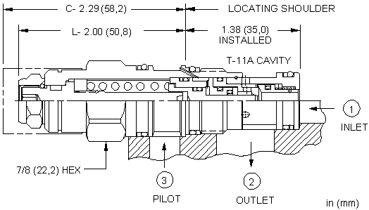
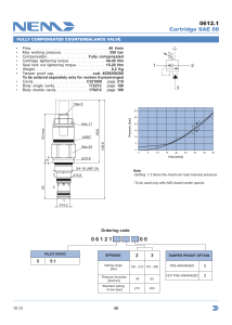
| Cavity | T-22A |
|---|---|
| Series | 2 |
| Capacity | 30 gpm (120 L/min.) |
| Maximum Operating Pressure | 5000 psi (350 bar) |
| Maximum Valve Leakage at Reseat | See Technical Features |
| Check Cracking Pressure | 25 psi (1,7 bar) |
| Valve Hex Size | 1 1/8 in. (28,6 mm) |
| Valve Installation Torque | 45 - 50 lbf ft (61 - 68 Nm) |
| Seal kit - Cartridge | Viton: 990022006 |
How to read MWEMXIN
Sun part numbers are the model followed by one code per option. Hyphens, slashes and spaces are only dividers, so MWEMXIN, MWEM-XIN, MWEM XIN are the same part.
| Model | MWEM — Sun Hydraulics Vented, balanced, load control valve |
|---|---|
| Control | X — Not Adjustable |
| Minimum Control Pressure | I — 300 psi (20 bar) |
| Seal Material | N — Buna-N |
| Material / coating | Add /AP (stainless steel, passivated) or /LH (mild steel, zinc-nickel) to the end; no suffix is the standard finish. |
Control options
- X — Not Adjustable
Minimum Control Pressure options
- E — 75 psi (5 bar)
- G — 150 psi (10,5 bar)
- H — 200 psi (14 bar)
- I — 300 psi (20 bar)
- K — 450 psi (33 bar)
- M — 525 psi (36,7 bar)
Seal Material options
- L — Extended Temp. Buna
- N — Buna-N
- V — Viton
Material/coating options
- /AP — Stainless Steel, Passivated
- /LH — Mild Steel, Zinc-Nickel
- — Standard Material/Coating
Manifold & standard assemblies
Sun manifolds for cavity T-22A (70)
- N4A Sun Hydraulics Ninety degree with reverse flow check – reducing Line mount manifoldMWEMXIN-N4A — request assembly
- N4B Sun Hydraulics Ninety degree with reverse flow check – reducing Line mount manifoldMWEMXIN-N4B — request assembly
- N4C Sun Hydraulics Ninety degree with reverse flow check – reducing Line mount manifoldMWEMXIN-N4C — request assembly
- N4D Sun Hydraulics Ninety degree with reverse flow check – reducing Line mount manifoldMWEMXIN-N4D — request assembly
- N4I Sun Hydraulics Ninety degree with reverse flow check – reducing Line mount manifoldMWEMXIN-N4I — request assembly
- N4J Sun Hydraulics Ninety degree with reverse flow check – reducing Line mount manifoldMWEMXIN-N4J — request assembly
- N4K Sun Hydraulics Ninety degree with reverse flow check – reducing Line mount manifoldMWEMXIN-N4K — request assembly
- N4L Sun Hydraulics Ninety degree with reverse flow check – reducing Line mount manifoldMWEMXIN-N4L — request assembly
- N4T Sun Hydraulics Ninety degree with reverse flow check – reducing Line mount manifoldMWEMXIN-N4T — request assembly
- N4U Sun Hydraulics Ninety degree with reverse flow check – reducing Line mount manifoldMWEMXIN-N4U — request assembly
- N4V Sun Hydraulics Ninety degree with reverse flow check – reducing Line mount manifoldMWEMXIN-N4V — request assembly
- N4W Sun Hydraulics Ninety degree with reverse flow check – reducing Line mount manifoldMWEMXIN-N4W — request assembly
Technical features
- This valve has no relief function. Not even thermal expansion relief.
- Maximum valve leakage at reseat for I, K, M ranges is 5 drops/min. (0,3 cc/min.) at 200 psi (14 bar) below cracking pressure; E and G ranges is 3 cubic in/min. (50 cc/min.) at 50 psi (3,5 bar) below cracking pressure; H range is 3 cubic in/min. (50 cc/min.) at 75 psi (5 bar) below cracking pressure.
- E, G, H ranges are not meant for zero leak type applications.
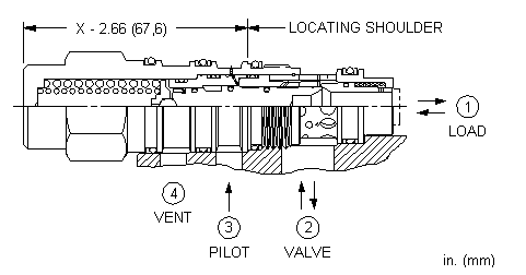
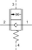
- This valve is balanced against load pressures and therefore exhibits self-compensation. Flow is controlled by the pilot pressure. Because of dynamic seals, performance is best in the meter out mode with port 1 being the load and port 2 being tank.
- All 4-port counterbalance, load control, and pilot-to-open check cartridges are physically interchangeable (i.e. same flow path, same cavity for a given frame size).
- This valve is a physical replacement for a counterbalance valve but probably won't work well in a cross-piloted cylinder application. A low pilot ratio is needed for machine stability and a balanced load control has an infinitely high pilot ratio.
- Applications that use a separate pressure source to the pilot have been successful in providing smooth and stable load control.
- Sun load control and counterbalance cartridges can be installed directly into a cavity machined in an actuator housing for added protection and improved stiffness in the circuit.
- This valve has positive seals between all ports.
- Incorporates the Sun floating style construction to minimize the possibility of internal parts binding due to excessive installation torque and/or cavity/cartridge machining variations.
Drawings, symbol & performance curves
Downloads
Datasheet
Technical reference sheets
- 999-901-334 (PDF 344 KB)
- FloatingStyleScrewInCartridge2 (PDF 1 MB)
- LH-QR-04082026_Ltr_EN-V2 (PDF 1 MB)
- TT_US_Cavity-New (PDF 522 KB)
- TT_US_Ctrbal_POCk_Jun2023_Final_0 (PDF 1 MB)
- TT_US_LAandLM (PDF 713 KB)
CAD files
Frequently asked questions
Is MWEMXIN the same as MWEM-XIN?
Yes. Sun Hydraulics writes this part number as MWEMXIN. It is the model MWEM followed by the configuration code; hyphens, slashes and spaces are only dividers, so MWEMXIN, MWEM-XIN, MWEM XIN all refer to the same product.
Do you supply MWEMXIN in the UAE, GCC and India?
Yes. MultiFlow supplies genuine Sun Hydraulics cartridges, including MWEMXIN, to customers in the UAE, the wider GCC and India. Use Add to Enquiry on this page for availability, lead time and a quotation.
Can I get the datasheet and CAD files?
Yes. The datasheet, technical reference sheets and CAD files (DXF, DWG, STP) are listed in the Downloads section of this page.
I have a pilot-to-open check on a large cylinder and the decompression is violent. Can I use a counterbalance instead?
No. The counterbalance will be less violent than the check valve but the flow dynamics create backpressure spikes that can damage the valve. The circuit needs to be designed to dissipate the energy in a controlled fashion.
When should I use a vented counterbalance valve?
Vented counterbalance valves should be used if you have backpressure in port 2 (inlet). Typical applications are regeneration circuits, master-slave circuits and servo/proportional valve circuits.
How do I determine the setting of a counterbalance valve?
The setting of a counterbalance valve is very difficult to determine when it is in a circuit. This is due to cross-piloting, load-induced pressure, and cylinder ratio. The best way to check the setting is to remove the valve from the circuit. Before removing any valve, ensure machines and loads are mechanically held in position and that the valve is not under pressure at the time of its removal. Screw the valve into a simple, single cavity, line mounted body. Port 1 should be connected to a pressure source and ports 2 & 3 should be open. Increase the pressure on port 1 until the valve just starts to open. Repeat several times to ensure consistency.
You say your valves leak 5 drops/min. How can I keep my load from drifting?
The 5 drops/min. are at the point of reseat which is 85% of cracking pressure. If the valve is set correctly it will never see a load that is higher than 77% of cracking (1/1.3). At this pressure, in a typical system the counterbalance can be considered a zero leak device. Using counterbalance valves to prevent drift is an accepted and common practice on almost all manlifts and hydraulically operated cranes. If a load drifts because of the counterbalance valve, the seat has probably been damaged and the valve should be replaced.
Should I replace the counterbalance valve if my cylinder is drifting or moving?
While cylinder drifting is often attributed to a leaking or damaged counterbalance valve, it can also be caused by cylinder seal leakage or changes in oil temperature. If you believe the seat of the counterbalance valve has been damaged, which can be caused by shock or contamination, it is advisable to replace the valve with a new factory set valve. Always follow the manufacturer's recommendations for servicing of hydraulically actuated machinery, and insure all loads are mechanically supported and cartridges are not under pressure when removed.
How big is a drop of hydraulic oil?
There are exactly 250 Sun drops in a cubic inch or 15 in a cc.
Why can't I block the pilot vent port? That area is positively sealed, isn't it?
Yes it is sealed; however every time the valve is cycled a small amount of oil passes into the spring chamber--about 1 drop for every 4000 cycles. If the vent is blocked, the spring chamber will eventually fill with oil, building pressure until the valve won't open.
How do I size a counterbalance valve?
Counterbalance valves are pressure dependent devices, not flow dependent. They are designed to create pressure drop for their operation, so it is important not to oversize them. A higher pressure drop will generate greater system stiffness and help improve stability.
How do I know how much pilot pressure is required to lower a load with a counterbalance valve?
Two areas work to open a counterbalance valve—the relief area and the pilot area. The pilot area divided by the relief area equals the pilot ratio. Reverse flow from port 1 to port 2 is blocked by the check valve until a pilot pressure is sensed at port 3 (pilot) that is inversely proportional to the load pressure at port 1 (load). The pilot pressure at port 3 effectively reduces the relief valve setting. The setting is reduced according to the ratio of the differential pilot area on the piston compared to the differential relief area. For example, in a valve with a 3:1 pilot ratio, set for 3000 psi with a load of 2000 psi, the pilot pressure required to open the relief valve is 333 psi—i.e., (3000 psi - 2000 psi)/3 = 333 psi pilot pressure.
To calculate the pressure required to lower a load, use the following equations. These equations are under ideal conditions and do not consider any backpressure in the circuit or any effects of temperature on the oil.
What do you mean by hysteresis when referring to a counterbalance valve?
Hysteresis is the difference between the pressure at which the valve will crack open and then reseat closed. Sun's counterbalance valve's hysteresis is typically less than 15%, which means the valve will have reseated to a closed position at 85% of its cracking or opening pressure.
Can I adjust a counterbalance valve in the field?
It is always recommended that a counterbalance valve be set before it is installed in an application. Correctly setting a counterbalance when it is installed is very difficult due to the pilot assist and the interaction with the actuator. Once installed the adjust screw should be considered a manual override.
Why can't I use a counterbalance valve in a closed loop transmission circuit?
A closed loop transmission is meant to transfer the energy from dynamic braking to the prime mover. A counterbalance valve would put the energy in the form of heat into the small amount of oil contained in the loop. Backpressure caused by dynamic braking from the pump and charge pressure complicate matters. "Putting a vented counterbalance in a closed loop transmission is a crime; putting a non-vented valve in is a felony; putting a 10:1 valve in is a capital offence." Jeff Baker
How does Sun test a counterbalance valve for leakage?
First the valve is set to just crack open at the desired setting. The pressure is dropped to zero and then brought up to 85% of the setting. The valve is then piloted open and allowed to reseat. At this point the leakage rate must be less than 5 drops per minute. One detail that makes this test critical is extremely clean oil. If a valve leaks in an application, the seat has probably been damaged by contamination and the valve should be replaced. Before removing any valve, ensure machines and loads are mechanically held in position and that the valve is not under pressure at the time of its removal.
What do you mean by the setting of a counterbalance valve and what should it be?
Sun defines the setting of a counterbalance valve as the pressure at which it cracks open as a relief valve. The flow rate at "crack" is the point where drops turn to a stream, about 1-2 cubic inches per minute. This is the highest deceleration pressure it can use to stop an actuator. The valve should be set at least 1.3 times the maximum expected load-induced pressure at port 1. In many cases the maximum load-induced pressure will be the same as the system relief setting.
Can I use an atmospherically vented counterbalance valve instead of the four-port version to save on plumbing?
Three-port vented, or atmospherically referenced, counterbalance valves are considered problem solvers for existing circuits that used a three port, non-vented valve. If a vented valve is required in a new design, four-port valves are recommended. Atmospherically referenced valves, over time, will leak externally or allow moisture into the spring chamber (resulting in corrosion) even though the spring chamber is sealed.
Why do you offer 2 check valve cracking pressures?
Generally, the 25 psi check spring is recommended for most applications as it is more robust and insensitive to rapid flow reversals. The 4 psi check cracking pressure should be used if there is a need to pull in make-up oil.
I don't need pilot assist. Can I just block port 3?
We do not recommend it. There is a possibility that the pilot area could get filled with oil and slow down or prevent the closing of the valve. A correct solution is to connect port 3, the pilot port, to port 2, the outlet port.
What happens to the counterbalance valve if I have backpressure in my system?
Backpressure at port 2 (inlet) may adversely effect the operation of a three port counterbalance valve as it directly opposes pilot pressure. When backpressure exceeds pilot pressure, it adds to the setting of the valve at a rate of 1 plus the pilot ratio times the backpressure, i.e. with 200 psi (14bar) back pressure at port 2 on a 3:1 counterbalance valve, the setting would increase by 800 psi (55 bar). In effect, backpressure drives the counterbalance valve closed. Using vented counterbalance valves typically will correct this problem.
How do I decide which pilot ratio to select?
The vast majority of counterbalance applications are satisfied with a 3:1 pilot ratio. Lower pilot ratios will increase system stability and higher ratios will be more efficient. 10:1 pilot ratio valves generally should be avoided.
Why is it that your valves have pilot ratios below 10:1, while other manufacturers start at 7:1 and go up?
There are 2 styles of load-reactive counterbalance cartridge valves. The first was designed by Racine and has the pilot in port 1 or the nose of the cartridge. The second style that Sun adapted was conceived by Fluid Controls, and has the load port (port 1) at the nose and the pilot coming in port 3. Sun co-founder John Allen said that a counterbalance was a valve designed around a spring. For a given size of cartridge you design a spring that has the most force and rate that can be wound, and then design the rest of the valve. The spring force dictates the relief area needed to achieve a setting.
The Racine design has 2 diameters. There is a pilot diameter and a larger diameter that creates the annular relief area. In order to maintain capacity the larger diameter has to be as large as possible. In order to increase pressure settings the annular relief area needs to be reduced. Because the big diameter is fixed and the differential annular area is being reduced, the result is the pilot diameter increases; hence the high pilot ratios.
Sun's (Fluid Control's) design has 3 diameters, the small one and the middle one defining the relief area and the middle one and the large one defining the pilot area. This design gives us the freedom to create pilot ratios that fit the application.
What parts of the Sun cartridge valve are field serviceable?
Why is turning the adjust screw for counterbalance valves opposite of most other valves?
Manufacturer reference: https://www.sunhydraulics.com/model/MWEM